Has anyone rewired a 1954 Hornet with Overdrive and figured out what kind of O.D. wiring harness is needed? Where did you get your replacement harness?
Some background detail:
Rhode Island Wiring supplied me with the other harnesses. They don't have a pattern for the 1954, and they are reluctant to send me a 1953 O.D. Harness (for which they do have a pattern). According to the 1948-1954 Hudson Parts Catalog, the Overdrive Wiring Harness for the 1954 Hornet is [b]not[/b] the same as the 1953 Hornet, even though electrically and mechanically they appear to be the same. They suggested that I send them my old harness to duplicate, but it was "Mickey Moused" in my car before I got it, so it is not really correct or attached in the right places.
Discussion moved to "Hudson" forum category.
Bob,
YnZ Yesterdays Parts lists a 1954 Overdrive Harness. They are great folks to work with, give them a call to answer your questions.
http://www.ynzyesterdaysparts.com/pdfs/Hudson.pdf
Hope this helps
John Forkner
There is another alternative to ordering you harness. The OD harness is pretty simple to construct. Using the information found on my website, you can rewire your OD is a day. [url= http://hudsonrestoration1948-54.com/Transmission.htm ] Ken Cates' Hudson Stepdown website[/url].
Save the unique connectors and use modern wiring of the proper gauge. Most of the harness is covered with a black tape so need to find or buy the more expensive cloth over modern wiring to create the harness. A few hours with a soldering iron and shinktubing should result in a fully functioning harness. BTW you can test your harness before putting it in with a meter or test ligth. Good Luck
Thanks! I decided to do it myself, per your suggestion, using reproduction cloth wire of the correct colors and gauge. The deciding factor was that I want to install a second kick down switch on the dashboard in addition to the one under the gas pedal. My first car was a 1961 Rambler Ambassador V-8 with overdrive, and the first owner had moved the kick down switch to the dash (from the carburetor linkage). It was much nicer pressing that button than jamming the accelerator to the floor, especially when going uphill at about 25 MPH under light load.
There are 2 pairs of wires on the Hudson O.D. kick down switch. The N.O. pair can be wired in parallel between the two switches, so either switch can complete the connection (to short out the coil momentarily) when the switch is pressed. The N.C. pair must be wired in series between the two switches, so that either switch can break the circuit when pressed.
BTW, I did not find the 1954 Hudson overdrive diagram on Ken's website, only a 1950-52 version. I have a 1954 wiring diagram from the body manual, but it is missing a critical part: the governor -- someone left it out and showed the lockout switch wired directly to ground, instead of via the governor to ground. So I had to use some logic and basic electrical circuit knowledge to come up with the correct wiring on my 1954.
There is one more tricky issue because my car was converted to 12 volts. Hudson apparently was concerned about the generator not charging at idle speed, so they used the A terminal on the voltage regulator to power the overdrive solenoid. I believe that's because the A terminal is only energized when the generator is charging the battery, so it prevents draining the battery if the generator can't keep up. But in a 12 volt conversion, there is no generator, and thus no A terminal, so I have to use power from the ignition switch instead of the A terminal. That should be okay because an alternator can charge the battery at idle speed, e.g. when freewheeling downhill.
That brings me to my final observation or question. The repair manual states that with a manual transmission, the idle speed for the 308 engine is 600 RPM, but it should be 650 - 675 RPM if you have overdrive. Now I think I understand why: it is related to the above issue with the generator not charging at normal idle speed. So to prevent the car from dropping out of overdrive due to the A terminal not being energized, they up the idle speed on the engine for O.D. cars! I am going to try to set the engine idle at the lower non-OD value since my alternator should be able to power the solenoid. That should also waste less gas when idling or coasting downhill.
Dr. Bob-
Your logic is sound and I agree with you.
Bob, I don't really know why they call it different from '53, same solenoid, same kick-down switch ,& location, same 2 lever trans, same W.B., same gas pedal, same relay, same firewall location??? Maybe it is as simple as picking up power from a different location or different color of wire?. Same, same, same,etc.... FYI, plug in for the kick-down and O/D relay are called Essex plugs.
I beleave if you are freewheeling the circuit is open and your o/d is not useing power,when in o/d drive at speeds over 17 mph it shoud not freewheel its locked in o/d, if you are freewheeling at road speed your o/d is not working, on the gas or off the gas it be ingauged
Dan
[quote="Dr. Bob Goldberg" post=16038]
BTW, I did not find the 1954 Hudson overdrive diagram on Ken's website,
Dr Bob the wiring diagram can be found in this posting on my website...
http://hudsonrestoration1948-54.com/1946-1954_wiring_diagrams.pdf
Doug, I tried searching the web for Essex plugs and couldn't find them. Do you know where I can get one?
Ken,
Clicking the link you gave above, I get the following error: Direct Linking to this page is NOT ALLOWED
I was able to find the wiring diagrams on your site by navigating from hudsonrestoration1948-54.com
=> Electrical System
==> Hudson Wiring Diagrams
Unfortunately, the writing on the diagram is very blurry, and the problem seems to be the resolution of the scan. Here is what it looks like:
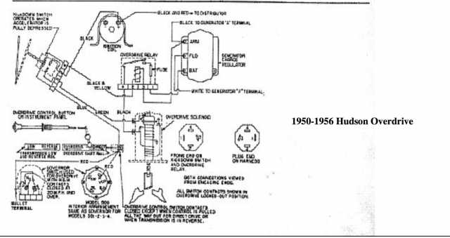
Dr Goldberg... could not post a high quality picture of the schematic here. I sent the diagram to your email address as a JPG attachement. It should allow you to view the diagram clearly on the computer and priint it as small or large sizes. The ESSEX plugs can be sourced from USED Hudson parts. Several vendors post on this forum.
Ken
[quote="Dr. Bob Goldberg" post=16065]Doug, I tried searching the web for Essex plugs and couldn't find them. Do you know where I can get one?
What Essex plugs do you want?
I've got new 18mm "long reach" spark plugs as originally used on late 20's Essex
Dave Young
[quote="Kenneth Cates" post=16070]Dr Goldberg... could not post a high quality picture of the schematic here. I sent the diagram to your email address as a JPG attachement. It should allow you to view the diagram clearly on the computer and priint it as small or large sizes. The ESSEX plugs can be sourced from USED Hudson parts. Several vendors post on this forum.
Ken
Ken,
Can you send me a copy please so I can try a post in the test site ; email address is HETpaul_hetclub@btinternet.com
Drop the HET as usual
[quote="Paul Butler" post=16083][quote="Kenneth Cates" post=16070]Dr Goldberg... could not post a high quality picture of the schematic here. I sent the diagram to your email address as a JPG attachement. It should allow you to view the diagram clearly on the computer and priint it as small or large sizes. The ESSEX plugs can be sourced from USED Hudson parts. Several vendors post on this forum.
Ken
Ken,
Can you send me a copy please so I can try a post in the test site ; email address is HETpaul_hetclub@btinternet.com
Drop the HET as usual
Paul I sent you the picture in question. Ken
